Wire and sinker EDM
This page is the reference for the EDM kinds of the operations ribbon: Wire Contour, the one kind in the Wire EDM group, and Sinker Burn and Sinker Side Burn (captioned Side Burn), the two kinds in the Sinker EDM group. For the tabs themselves and what a click picks, see that page; for what a refusal means in general, see Reading a refusal.
Lengths are in mm (inches in an inch document); feeds are in mm/min. The wire kinds come first; the sinker kinds follow from Sinker EDM.
Blue shows the operation travel; dashed orange shows approach and retract; gray shows the workpiece. These schematics are not generated NC paths and have no scale.
Wire EDM: the machine, the wire and the post
A wire EDM machine. Wire Contour needs a setup whose machine file
declares the kind wire_edm. The library includes Sodick ALC400G;
its travel and taper limit are stated, but conditions, wire diameter,
guide heights and EDM codes must come from your machine's documentation.
For another machine, supply a file with its own data (the keys are in
Machine types). The Wire EDM ribbon group
shows only when such a machine is mounted. On any other machine the
operation is refused ("a Wire Contour operation is wire EDM work; the
setup's machine is a ... - mount a wire EDM first"), and a wire EDM in
turn takes no other kind ("... - a wire EDM cuts only wire EDM
operations (a Wire Contour)").
No library tool. The wire is not a tool from the tool library: its diameter and the spark gap come from the machine's EDM condition, the one source for both. An operation that names a tool is refused ("a Wire Contour operation mounts no library tool - the wire is the machine's EDM condition; leave the tool empty (it names '...')").
Conditions. The machine file lists its conditions under
edm.conditions, each with an id and, for a wire cut, a gap (per
side) and a wire_diameter, taken from your machine's manual. No conditions ship.
CamCraft reads only those two numbers; power and flushing stay with the
control, which picks them by the condition's id.
Posting and checks. The built-in Generic ISO Wire EDM and Sodick
Wire EDM (Mark 21) posts serve wire machines. A user .cps post can declare
wireEdm = true; its manifest and machine support are checked before
posting. See Posting. Machine EDM codes and conditions
must come from the real control's manual. The program checks the wire's
kerf, profile, threading point, release plan and stated machine limits.
Simulate does not remove stock for wire work: the wire checks judge it.
The Sodick post supports vertical 2-axis cuts only. It refuses taper, 4-axis profiles, unsupported angle-word moves and control-side G41/G42 H-register offsets by operation name. CamCraft verifies its generated wire-centre path, not an offset chosen separately at the control. Same-path skim offsets are unsupported. When the wire machine states its Tank (submerged or non-submerged) and Flushing (high or low) in the machine editor, the Sodick post writes T94 / T89 and T84 / T85 after each threading, before the condition word; left unstated, they are not programmed and are set at the control. Tank fill, drain, flushing pump and wire-drive words are never written. Sodick output remains unverified on a real control.
Wire Contour
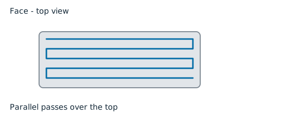

For: cutting one profile through the workpiece with a vertical or tapered wire. A die keeps the opening (the wire runs inside the profile and the slug falls out); a punch keeps the part (the wire runs outside it). The cut starts at a start hole, leads straight to the path, goes once round the profile counter-clockwise and leads back out the way it came.
Picks: the one closed profile to cut, on the Geometry tab. Without a pick it cuts the model's through-silhouette, which must then be a single outline. An open cut-off uses one open run that reaches the stock edge at both ends and Left or Right side. Run-out clearance states how far the threading point and run-out stand beyond the stock.
| Tab | Setting | Default |
|---|---|---|
| Geometry | Side | Die - the wire runs inside the profile; or Punch - the wire runs outside the profile |
| Geometry | Start hole stated | off |
| Geometry | Start hole X / Start hole Y | 0 / 0 when first ticked |
| Geometry | Taper angle | 0 degrees (vertical) |
| Geometry | 4-axis (upper and lower profiles) | off |
| Heights | Top of workpiece | model top |
| Heights | Bottom of workpiece | model bottom |
| Passes | Condition | (none chosen) |
There is no Lead in / Lead out tab and no Feeds tab: the lead is the straight line from the start hole, and the control's generator sets the cutting rate from the condition.
Kerf. The path is the wire centre: it stands wire radius + spark gap off the profile, on the side you state. The side is never guessed from the geometry. The generated path's notes give the side, the offset and its two terms, the kerf width (twice the offset) and the start hole.
Start hole. Type its X and Y; it is not picked in the viewport. For a die it is a hole in the slug, inside the profile; for a punch it is a hole or the stock's edge outside it. Either way it must stand more than the kerf offset off the profile.
Heights. One pass through the workpiece. The profile is read on the top, and the path is programmed on the bottom plane; the bottom must stand below the top.
Condition. The Condition list offers the conditions the mounted machine states. A condition the machine no longer states stays shown as "... (not stated by the machine)" until you pick another.
Passes and release. Add skim adds a pass after the rough cut. Choose each skim's condition, reverse flag and list order. Use the move and remove buttons to change that order. Skims cannot be combined with taper, 4-axis, tabs or burnout. Freed piece captured states that a catcher, magnet or machine retention catches the freed piece. Alternatively, Hold with tabs needs an explicit count, width, profile positions and Tab cut-off condition. Burn out the pocket (no core) removes the interior with offset rings; Wall clearance must be at least the kerf offset. An incomplete release plan is refused.
Taper. Positive Taper angle widens the profile downward from the
top plane; negative narrows it. The machine must state a maximum taper.
Setting a nonzero taper is refused at Apply if edm.max_taper_deg is
missing, the angle exceeds it, or a U/V machine has no guide planes.
U/V machines use their guide geometry. Angle-word controls instead need
an explicit positive-angle direction and corner rule in edm.taper_angle,
plus the taper codes. CamCraft models mitre and cone corner rules.
A cone lead-in that meets a corner is refused; move the start hole.
An angle-word control cannot cut different upper and lower profiles.
4-axis profiles. Pick one upper profile on the top plane and one lower profile on the bottom plane. Choose pairing by arc length or By sync points, and set Twist tolerance. Sync pairs can be typed or collected with Pick sync points in the viewport: click an upper-profile vertex, then a lower-profile vertex. Apply saves the pairs. A fan can hold one endpoint still while the other walks a span. Crossed pair order, identical rulings and an ambiguous whole turn at one endpoint are refused. Separate open runs are not stitched into a profile; select a face or one closed edge chain.
Where the two profiles turn against each other, a straight wire cannot lie in the surface between them: it stands off by up to the twist tolerance. Stand off says where. Only where the surface twists (the default) cuts every straight stretch to size and stands the wire off at the twist alone. The same all round stands every stretch off as far as the worst one needs. A twist that needs more than the tolerance is refused where it stands.
Verify tolerance. The check before posting reads the model's facets. A lofted model's facets stand past its true surface by up to the chord tolerance the model was faceted at, so a correct 4-axis cut can read as a gouge of a few microns. State that tolerance as the cut's Verify tolerance: the check then lets the kerf into the facets by that much and no more, and the report says the deepest reading it let pass. 0 (the default) checks the facets as they are. A gouge is always refused with the deepest reading at any height, so you can see whether the model's tolerance explains it. The value must be below the kerf offset and at most 0.25 mm.
Inside corners. No inside corner can be cut tighter than the kerf offset. A corner, slot or neck the wire cannot reach is refused by name, never rounded for you; round it in the model or cut with a thinner wire (another condition).
Wire Contour refusals
At Apply or creation, about the condition:
- "a Wire Contour needs a wire EDM machine mounted on its setup - the machine's EDM conditions state the wire diameter and the spark gap";
- "a Wire Contour names no EDM condition - choose one of machine ...'s conditions (it states ...)" - pick one on the Passes tab; "it states none - add edm.conditions to the machine file" means the machine file lists none;
- "machine ... states no EDM condition "..." (it states ...)" - the id is not in the machine file;
- "machine ...: EDM condition "..." states no gap" (or "no wire_diameter") - add the missing number to that condition.
At Generate, about the geometry and the start hole (each begins "wire contour:"):
- "no profile to cut";
- An open profile with Die or Punch side: use Left or Right for a supported open cut. Multiple closed profiles need separate operations and starts.
- "the profile crosses itself - a wire path cannot cross its own kerf";
- A profile with no area, or a neck, slot or inside corner tighter than the kerf allows: correct the profile or use a thinner wire condition.
- "no start hole is stated - a closed profile is cut from a threading point (...); the wire cannot be threaded through solid material" - tick Start hole stated and give X and Y;
- A start hole on the path or within its kerf offset: move the hole farther from the profile. A die threads inside the slug; a punch threads outside the kept part.
- "the workpiece's bottom (...) does not stand below its top (...)".
A message that names a place can be clicked to frame it. For other messages, see Troubleshooting.
Sinker EDM
A sinker (die-sink) EDM burns a cavity by feeding a shaped electrode down Z into the work; the electrode's face is copied into the part, a spark gap larger. CamCraft ships two sinker kinds: Sinker Burn, a plunge to depth (with an optional orbit at the floor), and Sinker Side Burn, the same plunge followed by one sideways move that pushes one wall out.
A sinker EDM machine. Both kinds need a setup whose machine file
declares the kind sinker_edm, and that file must state a Z axis ("Z
axis: required for a sinker EDM machine"). No sinker machine file ships.
The Sinker EDM ribbon group shows only when such a machine is mounted.
On any other machine the operation is refused ("a Sinker Burn operation
is sinker EDM work; the setup's machine is a ... - mount a sinker EDM
first"), and a sinker EDM takes no milling, turning, plasma or wire work.
The electrode is a library tool. Unlike the wire, the electrode is a
tool of the kind Sinker electrode in the tool library. Its face can
be a rectangular, sharp-cornered block or a closed outline extruded along
Z. The MCP command electrode_from_faces derives an electrode from cavity
faces, including rounded pockets, L shapes and rotated rectangles. Use
list_features to identify the level floor and every planar vertical
wall. Supply those picks, an undersize or a machine condition id (not
both), the holder stub and pickup offset. An optional orbit radius
also reduces the electrode outline. The burn check applies the condition's
spark gap to the derived face. On the tool page:
| Tool field | Means |
|---|---|
| Electrode X size | the burning face's size along X |
| Electrode Y size | the burning face's size along Y |
| Flute length | the electrode's length below the holder: the deepest it can burn without burying its holder |
| Shank length | the pickup offset, from the electrode's top face up to the pickup the control measures it from |
For a body electrode, X and Y are the outline's extents. The project and tool library retain that outline; changing a size without a matching outline is refused. The tool preview remains rectangular, so it does not show the body's actual section.
An electrode turns no spindle, so its rpm is 0 and it has no corner radius. The tool is refused when it says otherwise:
- "a sinker electrode turns no spindle - its rpm must be 0 (it states ...)";
- "a sinker electrode states its Y size in its width (it states ...); its diameter is the X size";
- "a sinker electrode's face is sharp-cornered - a corner radius of ... is not modelled".
A sinker operation mounts only a sinker electrode, and no other kind mounts one: "No sinker electrode in ...'s tools - a Sinker Burn operation cuts with one; add it to the tool library", or "'...' is a ...; a Sinker Burn operation cuts with a sinker electrode".
Conditions. The machine file lists its conditions under
edm.conditions, as for a wire EDM. A sinker condition states a gap
(the spark gap per side, above 0 and at most 0.5 mm) and may state an
undersize (the electrode undersize per side it wants, at most 1 mm, not
smaller than the gap); it never states a wire_diameter ("wire_diameter
is a wire field; this is a sinker EDM machine"). The burn reads only the
gap: the electrode tip stops that far above the burn floor.
Orbits. A Sinker Burn may orbit at the floor. The machine file says
which patterns its control offers, under edm.orbits (each a kind -
circular, vector or planetary - and the control's own word for
it), and the largest orbit radius it allows, edm.max_orbit_radius.
Neither is assumed: a machine that lists no orbits takes none, and one
that states no maximum takes none either.
Posting. The "Sinker EDM (ISO)" post serves a sinker EDM, and it is
the only one that does: any other post stops with "... does not serve
..., a sinker EDM machine". It writes the motion words itself and takes
every EDM code from the machine file's edm.codes - the unit word
(metric / inch), pickup ({tool}), reference ({offset}),
condition ({id}), depth ({z}, optionally {f}) and end. A
code the machine does not state stops the post by its name. It writes a
straight Sinker Burn only: a condition the machine's edm.conditions
does not list, an orbit and a Sinker Side Burn are refused by name. Not
exercised on a real EDM control.
Verification. The program verdict cuts the stock with the electrode's face, grown by the spark gap, at every move. A body electrode uses its actual outline; a rectangular electrode uses its box. The stock view does not draw a sinker electrode yet and says so: "the stock view has no sinker electrode atom yet - the program verdict (the column engine's box atom) judges the burn".
Sinker Burn

For: burning a cavity the shape of the electrode's face, straight down Z. The electrode rapids to the approach plane above the burn point, feeds down to the burn depth (its tip a spark gap above the burn floor), optionally orbits there to open the cavity sideways, and rapids back up. Choose it for a blind cavity, rib or detail a milling cutter cannot reach; one operation is one plunge at one point.
Picks: none. The burn point is typed as X and Y; it is the centre of the electrode's face.
| Tab | Setting | Default |
|---|---|---|
| Geometry | Burn at X / Burn at Y | 0 / 0 |
| Geometry | EDM condition | (empty) - type the machine's condition id |
| Heights | Approach plane | the draft's clearance plane |
| Heights | Work top | model top |
| Heights | Cavity floor datum | model bottom |
| Passes | Depth from | Work top (depth down); or Cavity floor (stand-off up); or Electrode tip (down from approach) |
| Passes | Depth | 5 mm |
| Passes | Orbit | None (plain plunge); or Circular, Vector, Planetary |
| Passes | Orbit radius | 0.1 mm when a pattern is first picked |
| Passes | Vectors (Vector only) | 4, from 1 to 72 |
| Passes | Turns (Planetary only) | 1, from 1 to 20 |
| Feeds | Servo feed | 50 mm/min |
There is no Lead in / Lead out tab: the electrode enters straight down.
Depth. The depth is read from the datum you choose: down from the work top, up from the cavity floor datum (a stand-off left above it; 0 burns exactly to it), or down from the approach plane. Whichever you choose, the burn floor may not pass the cavity floor datum or the model's lowest point, and it must lie below the work top.
Orbit. A circular orbit runs once round a circle of the orbit radius at the burn floor; a vector orbit goes out and back along the given number of evenly spaced directions; a planetary orbit spirals out over the given number of turns and then runs the circle. Each returns to the centre before the retract. The pattern must be one the machine lists and the radius within its maximum.
The generated path's notes give the depth and datum, the burn floor and tip Z, the spark gap and the cavity floor datum, and the orbit's pattern, radius and move count.
Rough and finish sizing. Electrode pass selects Single electrode, Rough (undersized) or Finish (to size). Rough and Finish also state Finished cavity X/Y. The condition's undersize sizes the electrode. The size check includes twice the sum of spark gap and XY orbit radius. A rough must stay inside the finished cavity; a finish must reach its size. The tip's floor stand is undersize minus orbit radius. A finish vector orbit needs a direction count divisible by four to reach all four walls. An orbit that overburns or leaves a finish short is refused.
Layers and wear. Layer step can divide the plunge into layers. Measured wear and Measured over state length lost over burned depth. Both values are required together. Measured wear takes priority over the condition's rate; with neither, the burn is uncompensated. The path notes state the rate, layer step, deepest commanded tip and remaining electrode length. Compensation still obeys the floor and electrode-length checks.
Sinker Side Burn

For: moving one wall of a burned cavity outward by a small amount, after the plunge. The electrode plunges as a Sinker Burn does, then feeds sideways along one axis by the amount you state, comes back to the centre, and rapids up. Choose it to finish or size one side of a cavity with an electrode made undersize; for an even enlargement on every side, orbit a Sinker Burn instead.
The Geometry, Heights and Feeds tabs, and Depth from and Depth on Passes, are the Sinker Burn's, with the same defaults. In place of the orbit, Passes has:
| Tab | Setting | Default |
|---|---|---|
| Passes | Burn wall | +X wall; or -X wall, +Y wall, -Y wall |
| Passes | Wall moves by | 0.1 mm |
| Passes | Electrode undersize | 0.2 mm (per side) |
Allowance. The electrode is smaller than the finished cavity by its undersize on each side; the spark gap already uses part of that. So the wall may move by at most the undersize less the condition's gap. A larger move would burn into the part and is refused by name, never shortened for you. The seed numbers are a draft to edit, not values for your machine.
The generated path's notes give the move and its wall, the burn Z and tip Z, the undersize, the spark gap and the allowance left.
Side Burn also offers Layer step, Measured wear and Measured over. Only measured axial wear applies; the condition's wear rate alone does not compensate a side burn. The lateral move and return run at the last compensated tip. Side wear does not lengthen the lateral move.
Sinker refusals
At Apply or creation, a side burn's numbers (each begins "sinker side burn:"):
- "a lateral amount of ... moves no wall - state a positive, finite amount";
- "an electrode undersize of ... per side is not a finite, non-negative number";
- "a lateral move of ... toward ... burns into the part - it exceeds the electrode undersize ... per side";
- once a condition is named, also the condition and allowance refusals listed under Generate below.
At Generate, about the machine and the condition (the side burn's say "Sinker Side Burn"):
- "a Sinker Burn burns on a sinker EDM; the setup's machine is a ...";
- "the Sinker Burn names no EDM condition - name one of machine ...'s conditions (its spark gap places the electrode)" - type one on the Geometry tab;
- "machine ... states no EDM section, so no condition "..."" - add an
edmsection withconditionsto the machine file; - "machine ... states no EDM condition "..."" - the id is not in the machine file;
- "machine ...: EDM condition "..." states no gap" - add the gap to that condition.
About the orbit (Sinker Burn only):
- "machine ... lists no ... orbit under edm.orbits - burn without an orbit, or pick a pattern the machine offers";
- "machine ... states no maximum orbit radius (edm.max_orbit_radius) - a ... orbit cannot be checked against it";
- "the ... orbit radius ... exceeds machine ...'s maximum orbit radius ...";
- "sinker orbit: a ... orbit of radius ... moves nothing - state a positive radius".
About the depth and the electrode (each begins "sinker burn:"):
- "a depth of ... from the ... burns nothing - state a positive depth";
- "the servo feed ... must be positive";
- "the cavity floor datum (...) stands above the work top (...)";
- "a depth of ... from the ... reaches Z ..., past the cavity floor datum at Z ..." - burn less deep, or lower the datum if the cavity really goes deeper;
- "a depth of ... from the ... reaches Z ..., past the model's floor at Z ...";
- "the burn floor Z ... does not enter the work (its top is Z ...)";
- "the approach plane Z ... must stand above the work top Z ..." - raise the approach plane on the Heights tab;
- A spark gap as large as the burn depth: burn deeper or select a smaller gap so the electrode enters the work.
- A burn deeper than the electrode length: use a longer electrode or burn less deeply so the holder stays above the work.
About the side burn's allowance (each begins "sinker side burn:"):
- A gap larger than the electrode undersize: choose a condition whose gap fits the undersize.
- A move larger than undersize minus gap: move the wall less or use a more undersized electrode.
- "a Sinker Side Burn moves along one axis - it takes no orbit (orbit with a Sinker Burn)".