2D milling operations
This page is the reference for the kinds in the Milling 2D and Drilling groups of the operations ribbon (Probe has a page of its own to come). For the tabs themselves and what a click picks, see that page; for what a refusal means in general, see Reading a refusal.
Lengths are in mm (inches in an inch document), feeds in mm/min (in/min). The defaults below are what a freshly created operation starts with: feed 1200, plunge feed 300, climb milling on, clearance 25 above the stock top, top at the model top, bottom at the model bottom, stepdown 5, stepover 3 and, where a kind has one, a retract plane 10 above the stock top. A retyped operation keeps the numbers it already had. Pocket, 2D Adaptive and 2D Offset size their entry helix to 0.4 x the tool radius when created with a tool.
Every kind checks its tool. Face, Contour, Pocket, Adaptive, Offset, Slot,
Trochoidal slot, Circular and Bore cut with a flat end mill or bull-nose;
Trace and Engrave take any mill or a taper tool. A wrong tool is refused by
name ("'
Use Ctrl+click to build a feature selection from multiple edges. CamCraft accepts the first edge even when that edge alone cannot define a region; Generate checks the completed selection. An armed Boundary row accepts faces and edges regardless of the toolbar's pick mode. Its open boundary can hold separate chains that keep the area between them. Crossing, touching or ambiguous chains are refused; Contour still rides one open boundary chain. Include and Exclude boundaries must remain closed.
Blue shows the operation travel; dashed orange shows approach and retract; gray shows the workpiece. These schematics are not generated NC paths and have no scale.
Face
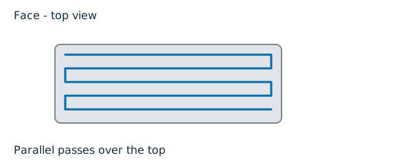

For: skimming the top of the stock flat, usually the first operation. Choose it over a pocket when the area to clear is the whole stock top, not a region inside the part.
Picks: none needed. It faces the whole stock outline by default; picks bound it to a smaller area.
| Tab | Setting | Default |
|---|---|---|
| Heights | Cut Z | stock top + 0 |
| Heights | Stage down to Cut Z (Top Z, Stepdown) | off: one level |
| Passes | Stepover (Y spacing) | 3 |
| Passes | Holes | Lift over (or Cut across air, lift over islands; Cut straight through) |
Common refusals: "staged facing needs a positive stepdown"; "staged top below the finished height"; "clearance plane not above the first cut level".
2D Contour

For: one wall, inside or outside, followed at a set of levels: profiles, bosses and bores. Choose it over a pocket when only the wall needs cutting.
Picks: faces or closed edge chains for the wall; an open chain can be added as an open boundary.
| Tab | Setting | Default |
|---|---|---|
| Geometry | Side | Auto (Inside, Outside); Auto may resolve to Inside from the picked rings, and says so |
| Geometry | Tolerance | 0.01 |
| Heights | Retract Z (between passes) | stock top + 10 |
| Heights | Stepdown | 5 |
| Passes | Stock to leave | 0 |
| Lead in / Lead out | Lead in/out | Linear, length 8 (None, Arc, Tangential, Perpendicular) |
| Lead in / Lead out | Tab count / width / height | 0 / 5 / 1 |
| Lead in / Lead out | Entry | Plunge, helix radius 1 |
Side Auto on a picked ring reads the part at the ring's own level. It looks just under the top and just over the bottom of the picks' height span and asks which side holds material. A blind-bore rim is therefore cut from inside, even though the bore floor fills the part's outline from above. If the two levels disagree, or material is on both sides, Auto refuses by name: "Side Auto cannot tell which side of the picked ring holds the material at Z ...: ... - set Side to Inside or Outside". Set Side yourself then. If no level shows material either side (a sheet part), the part's outline decides.
A picked ring whose chosen side stands in the part at every level is refused too, instead of cutting only the top plane in air. For example, Outside on a hole wall: the message names the ring, the part top and the fix: "the picked ring at (x, y) meets its wall at no level below the part top Z ...: the cutter Outside this ring stands in the part material - if the ring bounds a hole, set Side to Inside; else check the tool containment". A whole-model Contour is unchanged.
An open run picked on a part cuts on its air side, offset by the tool radius plus stock to leave. For a run picked on the stock instead, Side chooses the offset: Inside goes toward the stock and Outside goes away from it. Auto goes away from the part; it needs a part whose side is clear at every level. An ambiguous side is refused. Inspect the generated path before posting. CamCraft refuses an open run whose air side changes or whose offset cuts the kept part. A part-source run with no part material beside it keeps a centreline ride and the path notes say so.
An inside Ramp entry descends along the lead and ring at the entry angle. An unset entry angle means 3 degrees, independently of the link angle. If there is too little room for that ramp, the path reports its substitution and uses the plunge feed. Read the generated entry notes.
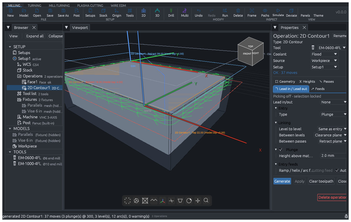 Before: Lead set to None plunges directly onto the contour.
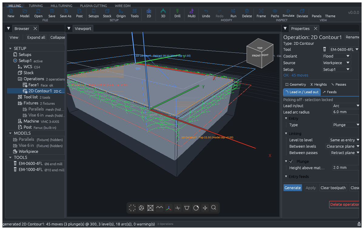 After: Arc lead-in enters tangentially from clear stock.
Common refusals: "the bore is narrower than the tool - switch Side to Outside or pick a smaller tool"; "cannot cut the gap at (x, y): it is narrower than the tool's ... diameter"; "a Contour's open boundary must be an open chain".
2D Pocket

For: clearing the inside of a closed area down to a floor, with islands left standing. Detect pockets / slots on the Model page finds pockets and creates one per row.
Picks: a floor face or a closed edge chain; an open chain is refused for an include or exclude boundary.
| Tab | Setting | Default |
|---|---|---|
| Passes | Strategy | Auto (Zigzag, Waterline, Adaptive, Offset rings); Auto takes Waterline for a round outline, Zigzag otherwise |
| Passes | Stepover | 3 |
| Passes | Stock to leave | 0 |
| Passes | Optimal load (% of D) | about 14.6 (used by Adaptive and Offset rings) |
| Heights | Stepdown | 5 |
| Lead in / Lead out | Entry | Helix, radius 1 (Plunge, Ramp, Arc) |
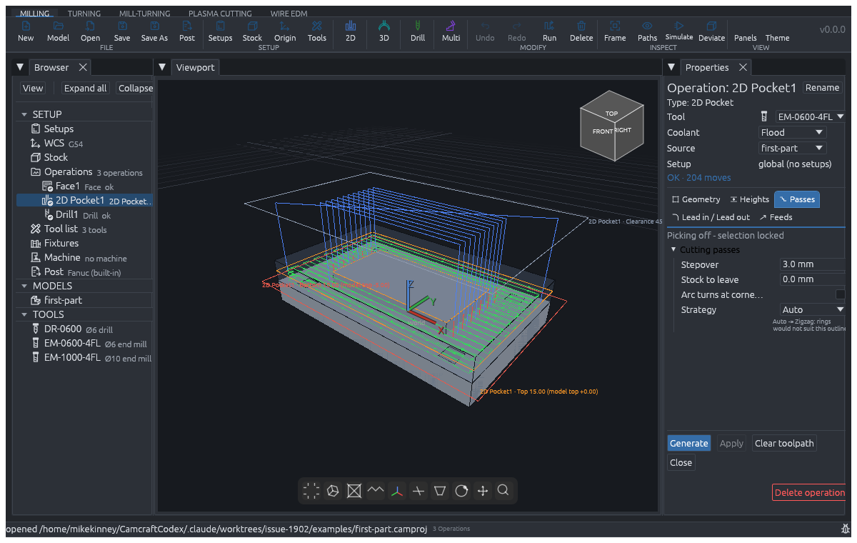
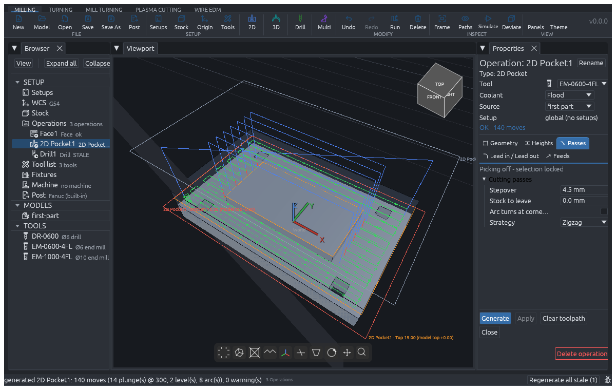 Before: wider stepover (4.5 mm) spaces passes further apart.
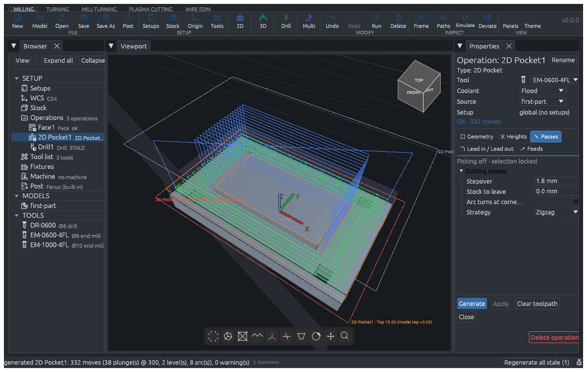 After: smaller stepover (1.8 mm) packs passes closely across the floor.
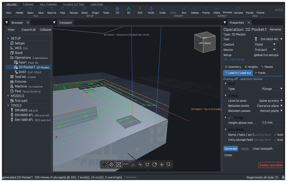 Before: Plunge entry dives straight along Z.
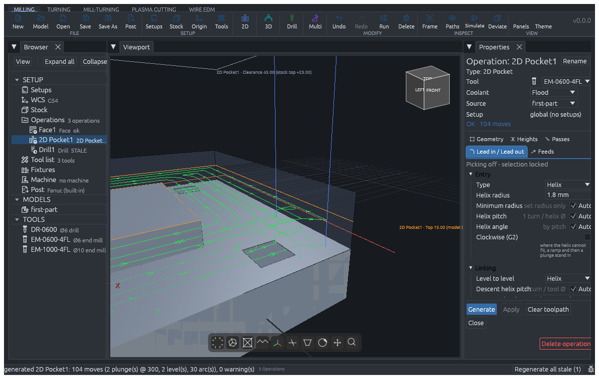 After: Helix entry spirals down along the programmed radius.
Common refusals: "pocket is narrower than the tool"; "stepover leaves bands the tool cannot reach"; a pick that "projects to a line from above and bounds no area".
Pocket, 2D Adaptive and 2D Offset can also use two open part edges as the walls of a band. The stock outline closes its ends. Both walls must be level at the same height and run alongside one another without crossing. Extend past extends the band's open ends along the walls, without widening it. With zero extension, the tool centre stops a radius inside the stock edge; an extension of at least one radius clears that edge. Mixed open and closed picks, ambiguous bands and tool containment On or Outside are refused.
A U-shaped blind slot can use its floor face or all three rim edges. The two side walls and closed end define the slot; the stock outline closes its open mouth. Extend past opens that mouth beyond the stock edge. A missing wall, unequal wall heights or an ambiguous mouth is refused.
Arc turns at corners and links rounds pocket-family corners. Its optional Arc radius defaults to the tool radius when unstated. A stated radius must be at least 0.01 mm and no larger than the tool radius. The path notes report corner material left by the rounding. Adaptive's Trochoidal method refuses this option because its loops already supply the arc motion.
2D Adaptive

For: roughing a pocket with a constant side load on the tool, so it can run deeper and faster than a fixed stepover allows. Choose it over Pocket for hard materials or deep roughing; it is Pocket's machinery with the spacing set by the load.
Picks: as Pocket.
| Tab | Setting | Default |
|---|---|---|
| Passes | Optimal load (% of D) | about 14.6 |
| Passes | Stock to leave | 0 |
| Heights | Stepdown | 5 |
| Lead in / Lead out | Entry | Helix, radius 1 |
Method chooses Spiral or Trochoidal. Trochoidal follows the pocket's medial lanes, including parallel branches around islands, then cleans up corners. With Method = Trochoidal, these additional controls appear:
| Tab | Setting | Default |
|---|---|---|
| Passes | Max engagement | 90 degrees; the forward step tightens to hold this limit |
| Passes | Loop width | All the room; optionally limit the band swept by loop centres |
| Passes | Return | Auto: a 0.3 mm microlift if clearance permits, otherwise Retract |
| Passes | Microlift height | 0.3 mm when Microlift is selected |
| Feeds | Return feed | Cutting feed; optionally state another feed |
Max engagement must be above 0 and at most 180 degrees. A stated loop width must be positive; the available channel limits its actual width. A microlift above clearance is refused. Choose Retract when the return must rise higher. These controls do not apply to Spiral.
Common refusals: as Pocket.
2D Offset

For: roughing a pocket in concentric rings from the boundary inward at a fixed stepover. Choose it over Adaptive when an even offset pattern is wanted rather than a constant load.
Picks: as Pocket. Settings: Stepover 3, Stepdown 5, Stock to leave 0, Entry Helix radius 1. Common refusals: as Pocket.
Slot

For: a straight slot of a given width between two points. The slot is typed in or seeded from suitable picked slot geometry; Detect pockets / slots can create one along a recognised slot's centreline.
| Tab | Setting | Default |
|---|---|---|
| Geometry | A X, A Y / B X, B Y | (-20, 0) / (20, 0) |
| Geometry | Slot width | 4 |
| Geometry | Extend past A / Extend past B | 0 / 0 |
| Passes | Stepover / Stock to leave | 3 / 0 |
| Heights | Stepdown | 5 |
| Lead in / Lead out | Entry | Plunge, helix radius 1 |
The A and B fields sit in their own Manual section on the Geometry tab; Slot width and the extension rows stay outside it. While the Geometry tab is open on the operation, with nothing picked and Properties visible, the viewport marks A and B with crosses and draws the line between them. The marks follow each edit before you choose Apply. They are display only; the committed edit is the undoable parameter change.
Common refusals: "slot is narrower than the tool"; "slot width must be positive".
Extend past A and Extend past B run the pass beyond each end, along the slot's length. Values must be finite and non-negative. Extensions still pass through the part checks. An extension into kept material blocks posting.
Trochoidal slot

For: a slot wider than the tool, cleared with small looping passes that keep the tool's engagement low. Choose it over Slot in hard material or when a full-width slotting cut would overload the tool.
Geometry: typed in like Slot.
| Tab | Setting | Default |
|---|---|---|
| Geometry | A / B | (-20, 0) / (20, 0) |
| Geometry | Slot width | 16 |
| Geometry | Loop width | All the room (the width less the tool) |
| Heights | Stepdown | 5 |
| Passes | Forward step | 1 |
| Passes | Max engagement | 90 deg |
| Passes | Return | Microlift, height 0.3 (or Retract) |
| Passes | Smoothing radius | 1 |
| Feeds | Return feed | 2 x the cutting feed |
Common refusals: "the channel ... is too narrow for a ... tool to loop in - cut it as a plain Slot"; "a loop width of ... leaves the channel"; "a ... mm microlift would feed the return above the clearance plane ... use the Retract return to hop higher".
Trace

For: running the tool's centre exactly along picked edges at a depth: grooves, scribed lines, cutting along a chain. No tool offset is applied, so any mill or a taper tool may be used.
Picks: edge chains, open or closed. Settings: Top Z, Bottom Z and Stepdown 5 on Heights, feeds on Feeds. It has no Passes tab. Common refusal: "empty trace region" when nothing usable is picked.
Engrave

For: the same centreline ride as Trace, named for engraving text and markings with a V-bit. Choose Engrave when the job is marking, Trace when it is a functional groove; the path is the same.
Picks and settings: as Trace.
2D Chamfer

For: breaking a top edge with a chamfer mill in one pass: the tool's cone lies on the chamfer face. Choose it over Deburr for a chamfer of a stated width on 2D edges.
Picks: the edges or faces whose top edge gets the chamfer. Needs a taper (chamfer) tool whose cone matches the angle.
| Tab | Setting | Default |
|---|---|---|
| Geometry | Chamfer width | 0.8 |
| Geometry | Chamfer angle | 45° |
| Geometry | Side | Auto |
| Geometry | Tolerance | 0.01 |
The floor is not set: it follows from the width and angle. It has no Passes tab.
Common refusals: "2D Chamfer rides its face on a cone - it needs a chamfer mill"; "a 45-degree chamfer takes a 90-degree cone; 'T5' has ... degrees"; "the cone of ... is ... mm of flute, short of the ... mm depth this face stands at".
Circular

For: a round pocket of a given centre and radius, cut in rings, with a flat floor or a domed one (Vault - dome floor). Choose it over Pocket when the circle is a dimension, not a model face.
| Tab | Setting | Default |
|---|---|---|
| Geometry | Center X / Center Y | 0 / 0 |
| Geometry | Radius | 25 |
| Geometry | Vault - dome floor | off |
| Passes | Stepover / Stock to leave | 3 / 0 |
| Heights | Stepdown | 5 |
| Lead in / Lead out | Entry | Plunge, helix radius 1 |
Common refusals: "circle radius must be positive"; "stepover must stay within the cutter radius - the last ring could leave an uncut core".
Thread

For: milling an internal thread with a helical thread mill. Choose it over a tap cycle for large threads, hard materials, or a machine without a rigid-tap spindle. The pitch comes from the tool.
Picks: holes, found with Detect holes. Tool: a thread mill (a tap tool carrying the pitch).
| Tab | Setting | Default |
|---|---|---|
| Heights | Bottom Z | each hole's own floor (override optional) |
| Passes | Radial infeed per pass | 0.1 |
| Feeds | Climb milling | on (a right-hand thread) |
Common refusals: "thread milling needs at least one hole"; "a thread mill needs a positive pitch to time its helix against"; "infeed must sit between 0 and the ... mm thread depth this pitch stands at".
Drill

For: drilling, spot drilling, tapping and cycle boring with canned cycles. Detect holes fills the hole list from the model; a new Drill starts empty and refuses to generate until it has holes.
| Tab | Setting | Default |
|---|---|---|
| Heights | R plane (feed starts here) | model top + 0 |
| Heights | Bottom Z | each hole's own floor; Override the hole floors to set one |
| Passes | Cycle | Auto: the tool decides (a tap taps, a boring bar bores, a drill chooses by depth against diameter); or Spot, Drill, Peck, Tap (rigid), Bore, Back bore, Tap (floating holder) |
| Passes | Peck depth | Auto (by the cycle) |
| Passes | Dwell at bottom | 0 s |
Tools: drill, tap or boring bar.
A cross drill can use a reduced-fidelity model when its mesh error leaves a positive verification tolerance. CamCraft increases the required stand-off, entry, reach and holder clearance to account for that error. It also tightens the part and radial rapid checks. If the error uses the full tolerance, import the model again at a higher step budget.
The Bore cycle (an expanded bore: feed in, then rapid out) needs a spindle stop before the retract. Heidenhain, TinyG and Carvera cannot do that, so they refuse it, with or without a dwell: "bore (G86) requires a spindle stop before rapid retract - expanded boring is not supported by this post; refused, not posted". Ordinary drilling stays available on those posts. Choose another post, or another cycle.
Common refusals: "no holes to drill"; "the tip meets steel ... past the mouth, short of the ... mm asked - ... match the depth and size to the model"; "tap leaves no thread core".
Bore

For: clearing and finishing a hole with an end mill smaller than the hole. Wide holes use concentric rings at each level; radial sweeps open each ring band and the last ring finishes the wall. Choose it over a Drill boring cycle when there is no boring bar of the right size.
Picks: holes, found with Detect holes.
| Tab | Setting | Default |
|---|---|---|
| Heights | Stepdown | 5 |
| Heights | Bottom Z | each hole's own floor |
| Passes | Stock to leave | 0 |
| Passes | Tolerance | 0.01 |
Common refusals: "boring needs at least one hole"; "clearance plane below a hole entry".
For a blind hole, the ring spacing uses the cutter's reach at the floor, so a bull-nose does not leave an interior floor ridge. Small holes keep a single ring when its floor bands meet. A plan needing more than 4,096 rings is refused before generation; review the hole and tool sizes.
A Bore Ramp entry zig-zags along the first radial sweep. An unset entry angle means 3 degrees. A separate link angle does not steepen it. If the sweep is too short, the path states that it substitutes a plunge at the plunge feed; the return descent to a ring is also named in the entry notes.