3D milling operations
This page is the reference for the kinds in the Milling 3D group of the operations ribbon: 3D Pocket, 3D Finish and Deburr. For the tabs themselves and what a click picks, see that page; for what a refusal means in general, see Reading a refusal.
Lengths are in mm (inches in an inch document), feeds in mm/min (in/min). The defaults below are what a freshly created operation starts with: feed 1200, plunge feed 300, climb milling on, clearance 25 above the stock top, top at the model top, bottom at the model bottom, stepdown 5 and stepover 3. A retyped operation keeps the numbers it already had.
All three kinds work from the model itself, not from picked loops: the area they work in is the model's shadow seen from above, and the levels, surfaces and edges come from the model's facets. Picking faces or edges does not draw a different region for them. 3D Pocket and 3D Finish take the Boundary settings on the Geometry tab (containment, offset, extra boundaries) to work a smaller area; Deburr has no area to bound.
In a part-aligned milling setup, 3D Pocket, 3D Adaptive and 3D Finish read the model, heights and area controls in that setup's frame. Picked source faces and Boundary controls are supported there. This does not enable operation-plane tilt or other unverified kinds; those still receive named refusals. See Setups.
Every kind checks its tool: 3D Pocket cuts with a flat end mill, ball-nose
or bull-nose, 3D Finish with a ball-nose only, Deburr with a chamfer mill.
A wrong tool is refused by name ("'
Blue shows the operation travel; dashed orange shows approach and retract; gray shows the workpiece. These schematics are not generated NC paths and have no scale.
3D Pocket
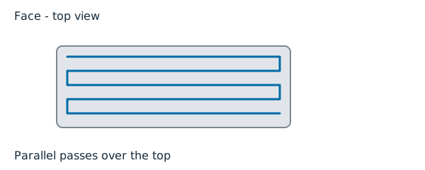

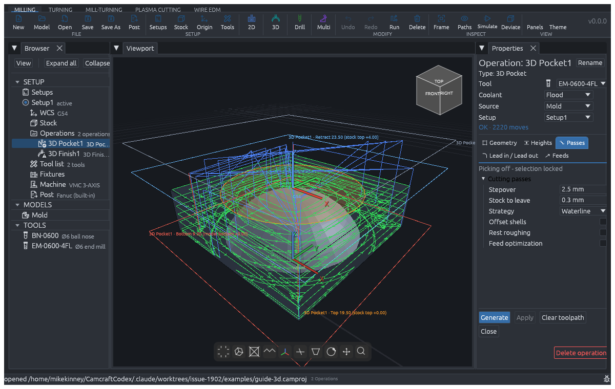
For: roughing a 3D part level by level, from Top Z down to Bottom Z. At each level the tool clears around the material that stands above it, so the levels follow the model's shape rather than one flat floor. Choose it over 2D Pocket when the part is a 3D shape, and leave stock for a 3D Finish to take.
Picks: none needed; it roughs around the whole model. Operations ahead of it in the program count: it only cuts where their material is still standing.
A whole-model roughing path clears out to the stock outline, including stock far outside the model's silhouette. At an open-sided notch it runs past the open edge so it does not leave a tool-radius ridge. Other parts remain protected; a path that cuts one produces a warning and cannot post. Picked and Boundary-controlled areas keep their stated limits. 3D Adaptive uses this same roughing path with its adaptive strategy.
| Tab | Setting | Default |
|---|---|---|
| Heights | Stepdown | 5 |
| Heights | Hop below clearance (Retract Z) | off: every link climbs to Clearance Z |
| Passes | Stepover | 3 |
| Passes | Stock to leave | 0 |
| Passes | Strategy | Auto (Zigzag, Waterline, Adaptive, Offset rings) |
| Passes | Optimal load (% of D) | about 14.6 (used by Adaptive and Offset rings) |
| Passes | Offset shells | off |
| Passes | Rest roughing | off |
| Passes | Feed optimization | off |
| Lead in / Lead out | Entry | Helix, radius 1 (Plunge, Ramp, Arc) |
| Lead in / Lead out | Between passes / Between levels | Keep down / Clearance plane |
Adaptive plans each level at a constant load; a level its planner refuses is cut with Offset rings, and the path says so. Offset shells lets the rings follow the model's surface between levels, so a steep wall is cut like a waterline instead of a staircase. Rest roughing adds a closing ladder at half the step for what the levels leave standing. Feed optimization slows heavier bites below the programmed feed (never above it).
Common refusals: "nothing to cut: the model fills the pocket at every level"; "nothing left to cut - the operations ahead in the program already machined this area"; "helix radius must be positive and at most the tool radius"; "optimal load must be in (0, 50] % of the tool diameter"; "retract plane sits inside the material".
When space remains but the cutter cannot fit, the refusal names the tool diameter and stock to leave. Use a smaller tool or reduce the allowance only if the job permits it. This differs from a model that fills every level, where there is no target to clear.
Before generating an upright 3D Pocket, CamCraft checks whether a wider shank or holder would reach material at Bottom of Part Z. Contact is also refused. The message names the tool and its shank or holder band: raise Bottom of Part Z or use a longer-reaching tool. This conservative depth check does not credit lateral room or material removed earlier, so a deep job can refuse even where there appears to be side clearance.
3D Finish

For: finishing 3D surfaces with a ball-nose, to a stated tolerance. One kind carries every finishing pattern; choose the pattern by the ground. Use it after a 3D Pocket has roughed the part.
Picks: none needed; the path covers the whole model. With Boundary settings, the whole-model path is clipped to the area, and it leaves and re-enters through the clearance plane.
| Tab | Setting | Default |
|---|---|---|
| Heights | Top Z / Bottom Z | model top / model bottom: the first ring's plane and the last level's |
| Heights | Hop below clearance (Retract Z) | off |
| Passes | Pattern | Parallel |
| Passes | Tolerance | 0.05 |
| Passes | Stepover | Auto: from tolerance and tool by the scallop law |
| Passes | Minimum step | Auto |
| Passes | Ramp between lines / Ramp ring entries | off / off |
| Passes | Ramp angle (when ramping) | 45° |
| Passes | Steep stepover (Steep and shallow only) | Auto |
| Passes | Reference ball (Pencil only) | None: every concave corner |
There is no stepdown: the levels drop by 2 x sqrt(tool radius x tolerance), so the cusp under the ball stays within the tolerance.
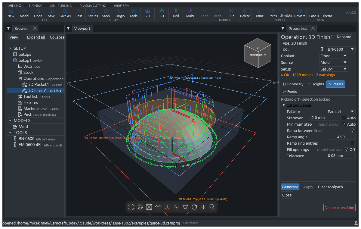
The patterns, in the Pattern list's order:
- Waterline: level rings on the walls only.
- Parallel, Parallel - multi, Scallop: lines over the flat ground first (along one axis, both axes, or the diagonals), then the rings take the walls. Ramp is Parallel with the sloped entries always on.
- Radial, Spiral, Morphed spiral: chords through the centre, one curve winding in, or that curve spaced by the slope under it.
- Contour, Project: concentric loops of the model's outline, or the outline lifted onto the surface.
- Steep and shallow: the rings stay off shallow ground, and the walls take their own spacing (Steep stepover).
- Blend: the lines keep the flat ground and the rings every run on ground past 30 degrees, so the band up to 45 degrees is cut by both and the border's staircase is shaved away.
- Flat: the floors only.
- Pencil, Corner: along each concave corner, cleaning what a fatter reference ball (Pencil) or the operation's own ball (Corner) leaves there.
- Geodesic: rings that march out from the model's open edge along the surface. A closed solid has no open edge and is refused.
- Morph: the waterline rings plus a guide halfway between each pair of levels.
- Flow: lines along the surface's own grain; on ground with no grain they become the straight raster.
Common refusals: "3D Finish needs a ball-nose tool, '
Deburr

For: breaking every exposed edge of the model with a chamfer mill: an open model's rim, or a convex crease where two faces meet. The cone lies on the break. Choose it over 2D Chamfer for a light break on the model's own edges at any height; choose 2D Chamfer for a chamfer of a stated width and angle on picked edges.
Picks: none. It finds the edges itself, and the Boundary settings are refused: there is no area to bound. It has no Passes or Lead in / Lead out tab.
| Tab | Setting | Default |
|---|---|---|
| Geometry | Break width | 0.5 |
| Heights | Window Top Z / Window Bottom Z | model top / model bottom |
| Feeds | Feed / Plunge feed | 1200 / 300 |
The depth is not set: the tip stands width / tan(half the cone angle) below the edge, so the tool's own cone angle decides it. The window is the pair of planes the tip rides between; an edge running outside it is clipped along its own line, not dropped whole.
Common refusals: "Deburr rides its cone over the edge - it needs a
chamfer mill"; "the break reaches ... mm up the cone's flank; '
On a reduced-fidelity model
A STEP model imported coarser than the importer promises is marked as reduced fidelity. 3D Pocket and 3D Finish are still checked against it, with their tolerances tightened by how much coarser it is: stricter, never looser. When the excess uses up a whole tolerance (for 3D Finish, its own Tolerance), the post refuses the operation: "model '...' was imported too coarsely to verify; re-import with a larger STEP facet budget". Deburr's checks do not read the excess yet, so it is refused on any reduced- fidelity model: "... this kind of operation cannot be verified against it; re-import with a larger STEP facet budget".