Indexed work: 3+1 and 3+2
Indexed work keeps the rotary axes still while the tool cuts. The tool or the part is held at one orientation for the whole operation, so the cut itself is ordinary 3-axis work. Use it for several faces of one part in one setup, for reaching an angled face, and for shorter tools on deep features.
CamCraft has one control for both kinds: the Tilted plane (3+2) group on a planar operation. It is not a separate machine mode.
Setting it up
- Mount a machine file with the rotary you need (see the shipped list).
- Add a planar operation. These accept the tilt: Face, 2D Contour, 2D Pocket, Slot, Trace, 2D Adaptive, Offset 2D, Engrave, 2D Chamfer and Circular. Drilling, the 3D and multi-axis operations, turning, Trochoidal Slot, Probe and Plasma do not carry one.
- In its properties tick Tilted plane (3+2). Set Tool axis A and Tool axis B (degrees) and the Plane origin X, Y and Z (the point the cut plane is anchored at, in world mm). A is limited to -90..90 and B to -180..180 at command creation; anything else is refused. C is left to the machine.
- Every move of the operation holds that one pose. The operation's picks, offsets and boundaries are read in the tilted plane, with the plane's own X and Y.
Each operation carries its own tilt, so one setup can hold several indexes: set a different tilt on each operation. Changing the tilt is an ordinary undoable parameter edit.
3+1 is a tilt with A set and B at zero on a machine with one A table
(doosan-dnm.mch, tormach-770mx-microarc4.mch). 3+2 sets both A and B
on a machine with two rotaries (tilthead.mch).
The work offset at each index
On a machine with a table rotary, the work offset is placed in the
setup frame, and the indexed post turns the table about the rotary's
centreline. tormach.cps writes its tilted path in the indexed frame, so the
work offset's Y0 and Z0 must lie on the A centreline; it says so in a note
at the first index. The index swing check makes the same assumption: the
WCS origin sits on the rotary's line.
How an index posts depends on the post:
tormach.cpswrites A alone, asG0 A..after a retract to the machine's safe Z, at the start of a section. It writes no A word on a cutting move. It refuses a B or C tilt, an A past the stated travel, an A that changes inside an operation, an arc under a tilt (a tilted path is chords) and a tilt on a machine with no A about X.fanuc.cpsanddoosan-dnm.cpswithmachine.rtcptrue armG43.4and write the angles (see Machines, kinematics and TCP).- Other posts refuse the tilt.
What is checked
- The machine check at post: a tilt on a machine that states no tilting rotary, an angle outside a rotary's travel, and a pose the machine's only rotary cannot reach are each named and block the post.
- Control-side cutter compensation does not ride a tilted 2D Contour: choose In computer.
- Tool shank and holder against the part and fixtures along tilted moves.
- The index swing: see Checks.
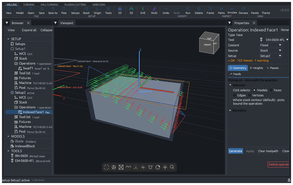
Unsafe example — do not post or machine. In
examples/guide-multiaxis.camproj, Indexed Face1 has 30 gouge warnings:
the cutter intrudes into the protected finish surface. This image illustrates
the fixed tilted pose and the warning state, not a verified facing recipe.
Before using this setup, align the tilted plane and its origin with the
intended face, then correct the cut depth and cutting boundary so the cutter
clears the protected finished model. Regenerate the toolpath and verify the
corrected operation with no gouge or collision warnings before posting or
machining. A posed program reported as "not judged" by stock simulation is
not a safety pass; see Checks.
Recipe: a three-sided block, 3+1
On a machine with an A table (for example the Tormach microARC 4 file).
- Clamp the block on the rotary and place the work offset on its centreline.
- Op 1: 2D Pocket or Face on the top, no tilt (A0).
- Op 2: copy it, tick Tilted plane (3+2), A = 90, B = 0, and set the Plane origin to the point on that face.
- Op 3: the same with A = -90.
- Run each operation, then Post.
The tilt letters stop at +-90 degrees, so an index reaches the top and the two sides, not the face opposite the top. For that face, flip the part: set the setup's part alignment to Flip over X in a second setup. (A part alignment is supported on Face, 2D Contour, 2D Pocket and 2D Adaptive.)
Recipe: an angled hole, 3+2
CamCraft's Drill operation carries no tilt, so a hole off the vertical is cut as a circle: on a machine with a tilt-head, add a Circular operation (a circular pocket about a stated centre and radius), tick Tilted plane (3+2), set A and B so the tool axis runs along the hole, set the Plane origin on the hole's entry point, and set the depth. A drilling cycle at an angle is not implemented.
Not implemented
- Tilted drilling cycles.
- Judging a tilted program in the stock simulation: a posed program is reported "not judged" by name rather than judged as if the tool stood vertical. The reach and shank checks above still run.